Doug F wrote:Thanks everyone! My funds are limited these days and I have a month to get it inspected so I can register it. With the wiring problems, I am torn to get a new harness or service manual! UGH!
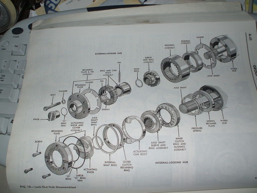
Money talks. (Or the lack of it.) Get the new harness and use free information when you can get it. The information in the other posts should give you what you need for the hubs. The diagrams mentioned are very similar to my 71. The text from my manual is below.
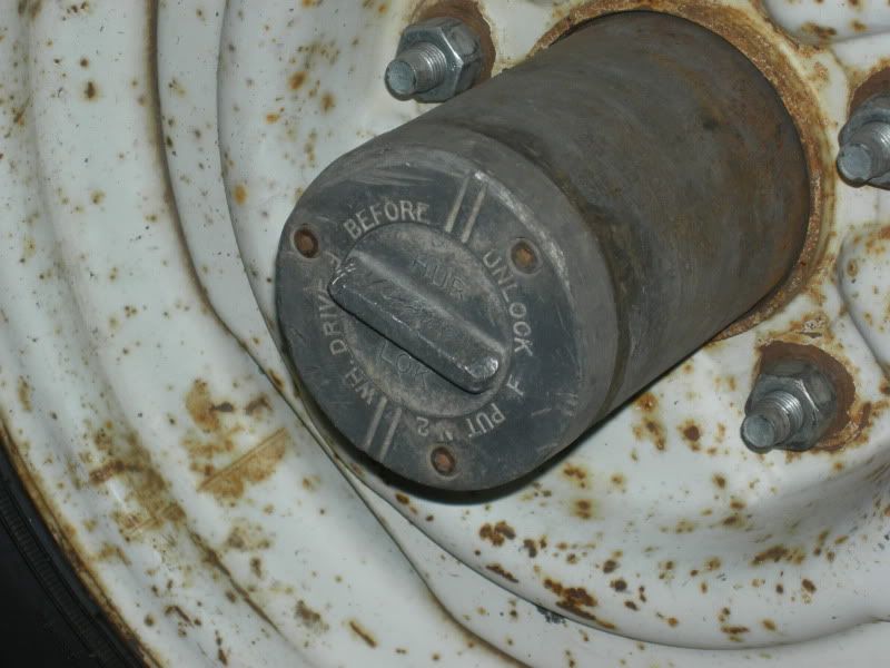
My purpose for removing the hub was to pack the wheel bearings. Other than that it didn't look like much could wear except the O ring. If your wheels are tight, you may be able to wait on this until after your inspection. Your wheel bearings should be inspected and packed.
I didn't see the nut in the drawings that needed the special wrench. It must be right against the wheel bearing. If I remember right, you need a wrench that is a circle with 4 knobs. I made the wrench by grinding the end of a pipe, leaving the 4 pieces sticking up. I think the pipe was 2" O.D. but check the amount of room in your hub. I welded a bar on the other end and a bolt so I could use a torque wrench. If you don't have a welder you could use a pipe wrench. You should follow directions and use a torque wrench but the torque specifications didn't work for me. When I backed it off as directed, the wheel was too loose. I ended up tightening it until the wheel spun but with some resistance then I backed it off until it spun freely but didn't feel loose.
I wish I had known about this forum when I was working on a lot of aspects of my truck!
4-Wheel Drive
Vehicles
1. Raise the vehicle and install
safety stands.
2. Back off the brake adjusting
screw, if necessary. Remove the wheel
cover, if installed.
3. Remove the front hub grease
cap. Remove the driving hub retaining
snap ring and slide the splined driving
hub from between the axle shaft and
the wheel hub (Fig. 4). Remove the
driving hub spacer. (If equipped with
free-running lock-out hubs, refer to
Front Wheel Drive Lock-Out Hub
Removal in 1971 Truck Shop Manual,
Group 15.
4. With Tool T59T-1197-B, remove
the lock nut and lock ring from the
spindle.
5. Using Tool T59T-1197-B and a
torque wrench, tighten the bearing
adjusting nut (Fig. 4) to 50 ft-Ib, while
rotating the wheel back and forth to
seat the bearings.
6. Continue rotating the wheel and
then loosen and re-torque the ad-
justing nut to 30-40 ft-Ib,
7. Back the adjusting nut off
approximately 112 turn (135-150
degrees). Assemble the lock ring by
turning the nut to the nearest hole
where the dowel pin will enter.
S. Install the outer lock nut and
torque to 50 ft-lb, Final end-play of
the wheel on the spindle should be
0.001 to 0.010 inch.
9. Install the driving hub, spacer,
snap ring and hub grease cap. Apply a
thin coat of non-hardening sealer to
the seating edge of the grease cap,
before installation. (If equipped with
free-running lock-out hubs, refer to
Front Wheel Drive Lock-Out Hub
Installation in the 1971 Truck Shop
Manual, Group is.
10. Adjust the brake, if backed off
to permit drum removal